The Project
An industrial monitoring manufacturer builds preventative-maintenance panels for electric heat tracing, the cable that keeps process piping and tanks above freezing through a winter. Their panels disconnect a heat trace circuit from power on a schedule, apply a 500 volt insulation resistance test to the cable, and trend the result over months. A falling megohm reading finds moisture working its way into a cable long before that cable draws enough leakage current to trip a ground fault breaker, which is the difference between a planned repair and a frozen line.
The measurement itself was the weak link. The test voltage was coming from a handheld meter with wires soldered onto its buttons, and an alternative module they tried would hang about once a day and need somebody to walk out and reboot it. They needed a purpose-built instrument on a DIN rail: 12 volt supply, 500 volt test, insulation resistance from tens of kilohms to hundreds of megohms, Modbus over RS-485, and above all no hangs.
Our Solution
We designed the instrument from a blank sheet. High voltage generation, the measurement front end, the safety architecture, the firmware, and the certification path were all in scope. The requirement that it never hang shaped the architecture from the start, because a monitoring device that needs somebody to walk out and reboot it is worse than no monitoring device at all.
The result is a board that makes its own high voltage, checks itself against on-board standards before every reading, and is designed so that the dangerous failure modes are bounded by physics rather than by software.
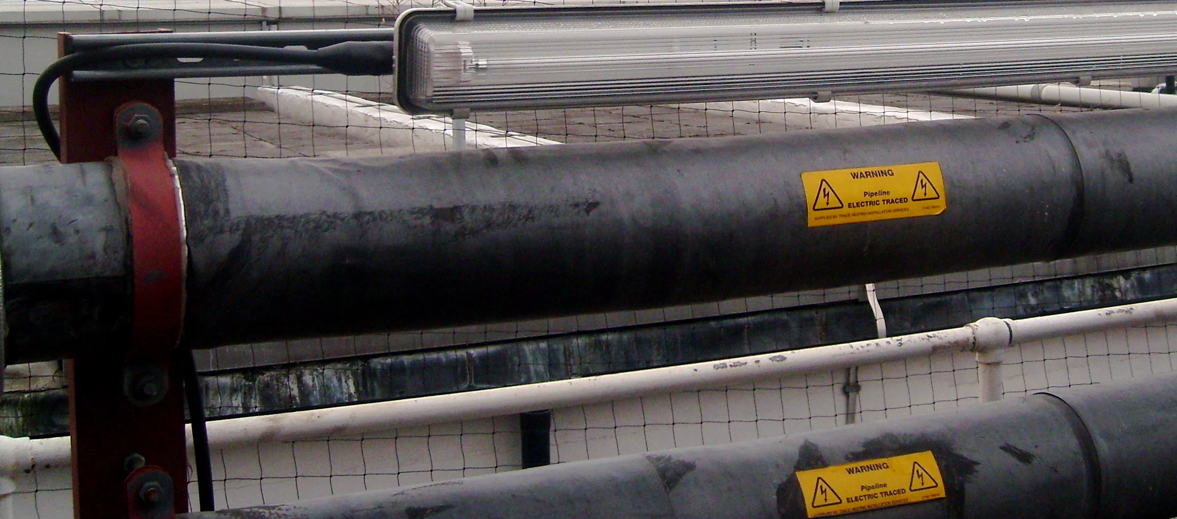
Electrically traced process pipework of the kind these panels monitor. Photo by Alan Myers, CC BY 2.0, via Wikimedia Commons.
High Voltage Generation
The high voltage comes from a custom flyback converter that takes the panel's 12 volt supply to anything from zero to just over 1000 volts. The processor programs the setpoint through a DAC into an analog error amplifier, and firmware servos the loop so that the cable under test sits at 500 volts no matter what its resistance turns out to be. That matters because a wet cable pulls the output down, and an instrument that reports the voltage it intended to apply rather than the voltage it actually applied will report the wrong resistance. On first silicon the stage regulates to within about one percent of setpoint across its range.
High Voltage Handling
Five things bound what the board can do to a person, to a cable, or to itself, and four of them work with the processor stopped.
Every path from the converter to the terminals runs through a high value limit chain, so a dead short across the output draws under two milliamps as a matter of arithmetic. An independent analog comparator watches the output on its own divider and kills the converter above a fixed trip point without asking the processor. The high voltage rail exists only while firmware is actively pumping a charge pump, so a stalled processor collapses the rail rather than leaving it live. A windowed watchdog power-cycles the processor rather than merely resetting it, which covers a latch-up that a reset pin cannot. And the discharge path carries its own energy reserve, so a board that loses power mid-test still dumps the cable in milliseconds instead of leaving a charged conductor for a technician to find.
The instrument also checks the line for live AC before it applies anything, and discharges automatically afterward. Heat trace cable recharges itself after a brief discharge through dielectric absorption, so the discharge stays engaged between tests rather than being pulsed once and forgotten.
Measurement
Resistance is computed as measured voltage over measured current rather than assumed voltage over measured current, and both quantities are read by the same 24-bit delta-sigma converter so that its reference cancels in the division. Accuracy then rests on the stability of a precision divider and shunt rather than on how well the converter regulates. Converter noise measures about five microvolts, which is a twenty-thousandth of the signal at the top of the range, so the analog-to-digital converter is not the limit on accuracy.
On-board precision standards switch into the measurement path so the instrument can verify itself before it trusts a reading. Across repeated runs the standards read back with a spread of about a hundredth of a percent. Near-end and far-end taps give a four-wire measurement of the switching chain and detect a severed connection, so the board can tell a genuinely open cable apart from its own broken wiring.
Results
First silicon regulates high voltage, passes a full production self-test, and measures real heat trace cable. A production cable read 13.2 gigohms at 503.5 volts, a leakage current of 38 nanoamps, which is three orders of magnitude above the five megohm pass threshold and shows the instrument has range to spare at the healthy end where trending actually happens. Calibration across the full measurement range is in progress ahead of the next board revision.
The design targets IEC 61557-2 for insulation resistance measurement and is laid out for UL 61010-1 and 61010-2-030 component recognition, with creepage and clearance held to the reinforced figures across a single high voltage boundary on the board.